MoTeC M1 AUDI V10 FSI BUJ / Lamborghini 07LY 2009 Package
Description
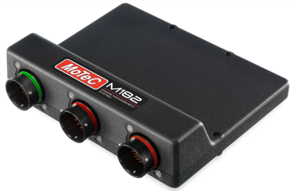
This package, used with an activated M182, provides a tuning base for the V10 BUJ and V10 07LY direct injection engine as used in the Audi R8 (2009 onwards), the Lamborghini Gallardo LP560-4 and the Lamborghini Huracan LP610-4. It comes with preconfigured settings for reference mode, synchronisation, firing order, DI pump control and engine sensors.
Based on MoTeC’s successful GPR-DI package, it is a versatile and adaptable platform for the operation of this engine.
Variants:
There is 2 variant available, which is:
- AUDI V10 FSI BUJ 2009 Package – M182
- Lamborghini 07LY Package – M182
Features:
-
Pre-configured sensor calibrations for Original Equipment (OE) sensors and engine triggers.
-
Pre-configured DI pump control.
-
Pre-configured control of the direct injectors.
-
Support of additional port injectors (‘high/low’) with tuneable balance table.
-
Pre-configured reference mode for engine synchronisation and control of 4 camshafts with tuneable inlet and exhaust timing tables.
-
Pre-configured physical settings for Engine Displacement, Fuel Density, Stoichiometric Ratio, Fuel Pressure, and Injector Linearisation, which allow for simplified engine start-up prior to tuning.
-
Comprehensive dual bank support – from airbox to inlet manifold all sensors, actuators and calculated engine control values are bank individual.
-
Configurable turbocharger boost control (using a normal and inverted solenoid output), support of 2 boost pressure sensors.
-
Fuel pump switched output and/or fuel pressure target closed loop control using PWM output.
-
Dual bank fuel canister purge solenoid support.
-
CAN transmits comply with version 3 of the general template.
-
Configurable on-board knock for each cylinder with up to 4 assignable knock sensors (hardware dependant) and 4 selectable centre frequencies.
-
Dual bank lambda control supported; requires optional LTC with Bosch LSU4.9 sensor or LTCN with NTK sensor.
-
Easy and fast engine tuning using engine efficiency map.
-
Engine load modelling based on inlet manifold pressure and inlet manifold temperature. Alternatively, for example, when using individual throttle bodies, throttle position can be used.
-
Fuel volume calculation considers delay effects resulting from the secondary (high) injector installation position.
-
Sensor calibrations available for many common automotive sensors.
-
Support for analogue and digital (frequency or duty cycle) sensors.
-
Transient fuelling compensation using physical modelling of fuel films.
-
Support of MoTeC devices: ADR, E8XX, PDM, SLM, V2
-
Configurable anti-lag for single turbo with ignition timing limit, fuel volume trim, ignition cut, engine speed limit, boost aim and throttle aim tables.
-
Supports 2 coolant fan outputs (PWM controlled).
-
Configurable closed loop alternator system for PWM field winding control.
-
Supports 2 switchable inlet manifold flaps with position feedback.
-
Air conditioner support with switched output control.
-
Coolant temperature compensations for engine speed limit, ignition timing, fuel volume, fuel mixture, boost limit.
-
Coolant pump output with PWM control.
-
Coolant pump after-run functionality, optionally with additional pump output.
-
Engine speed limiting with ignition cut and/or fuel cut.
-
Gearbox position detection via optional sensor or engine speed / wheel speed estimate.
-
Gearbox shift request via Up Shift Switch / Down Shift Switch or Gear Lever Force sensor.
-
Gearbox shift support with ignition cut, fuel cut, throttle blip and engine speed matching in forward gears.
-
GPS acquisition and logging via CAN or RS232.
-
Intercooler temperature and spray control.
-
Lap distance, time and number via BR2 or switched input, with split and sector options.
-
Configurable launch control with tables for engine speed, throttle limit, boost aim and fuel volume trim.
-
Race time system with tables for ignition timing trim, fuel mixture aim, boost limit and throttle limit.
-
Idle closed loop control system using ignition, drive by wire actuation or idle solenoid.
-
Engine Load Average channel with tables for engine speed limit, ignition timing trim, fuel mixture aim, boost limit and throttle limit.
-
Ease of engine start with dedicated fuel volume and idle compensations during crank and post start.
-
Engine run time total for engine hour logging.
-
Configurable security for multiple users with differing access options.
-
Configuration of brake state using a switch or a pressure sensor.
-
Configuration of clutch state using a switch, a position sensor or a pressure sensor.
-
Calculation of clutch slip.
-
ECU-internal G-force (acceleration) — longitudinal, lateral, vertical
-
ECU CAN receive from a defined CAN ID for data reception from MoTeC devices. Support of 3 CAN buses.
-
ECU CAN transmit of the most common channels using standard MoTeC CAN templates.
-
6 configurable switches, 4 rotary switches and 6 CAN switches with each of 9 positions simultaneously mappable to Launch Control, Pit Switch, Anti-Lag, Traction, Race Time Reset, Engine Speed Limit Maximum, Throttle Pedal Translation, Ignition Timing, Fuel Mixture Aim, Boost Limit, Traction Aim and Traction Control Range.
-
Pulsed tachometer output with configurable output pin and scaling.
-
Dual bank drive by wire throttle servo control.
-
Configurable throttle sensor input, with 2 channel analogue or single wire digital (SENT) protocol.
-
Throttle Pedal sensor with translation table. Hybrid OE pedals (for example Ford) are supported – one analogue and one digital channel.
-
Differential pump output with differential temperature threshold and hysteresis control.
-
Transmission pump output with transmission temperature threshold and hysteresis control.
-
Traction control with tables for Aim Main, Aim Compensation and Control Range.
-
Vehicle speed measurement using wheel speed sensors, estimation or GPS.
-
Vehicle speed limiting (pit speed control).
-
Configurable warning system with light and CAN output.
-
Auxiliary time system with tables for ignition timing compensation, fuel volume trim and fuel mixture aim.
-
4 auxiliary outputs for PWM control of added actuators:
-
Duty cycle tables using Engine Speed and Throttle or Manifold Pressure Axis’
-
Activation based on inlet manifold pressure or throttle position
-
Auxiliary Output 1 includes tables for Ignition Timing Compensation, Fuel Volume Trim and Fuel Mixture Aim
-
Optional channels for additional sensors via input pin and/or CAN message, including:
-
Airbox Mass Flow, Pressure and Temperature
-
Ambient Pressure and Temperature
-
Boost Pressure
-
Brake Pressure Front and Rear
-
Brake Switch
-
Clutch Pressure and Position
-
Clutch Switch
-
Coolant Pressure and Temperature Differential Temperature
-
Engine Oil Pressure and Temperature Engine Crankcase Pressure
-
Exhaust Pressure Bank 1 and Bank 2
-
Exhaust Temperature (EGT) via TCA Thermocouple Amplifier, Generic CAN, or E888 for Collector, Bank 1 and 2 Collector, and Cylinders 1 to 10.
-
Exhaust Lambda via LTC, LTCN, or PLM for Collector, Bank 1 and 2 Collector, and Cylinders 1 to 10
-
Fuel Pressure and Temperature
-
Fuel Tank Level (support for 2 level sensors)
-
Gear Position
-
Gear Lever Force
-
Gear Neutral Switch
-
Gear Shift Request
-
Inlet Manifold Flap Position x 2
-
Intercooler Temperature
-
Steering Angle and Pressure
-
Transmission Temperature
-
Turbocharger Speed
-
G-Force (acceleration) — Longitudinal, Lateral, Vertical Wheel Speed sensors front/rear left/right, wired or CAN input.

