Link ECU Plugin G4X Mazda MX5 NB1 – 240-4000
Original price was: AUD $2,299.45.AUD $2,189.95Current price is: AUD $2,189.95.
Description
Link ECU Plugin G4X Mazda MX5 NB1 – 240-4000
Easy to install. Affordable. Reliable.
G4X Plug-In ECUs offer the latest in engine management technology, designed to easily maximise the potential of your car.
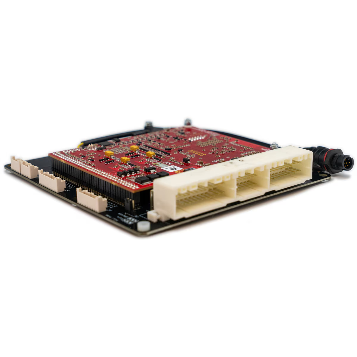
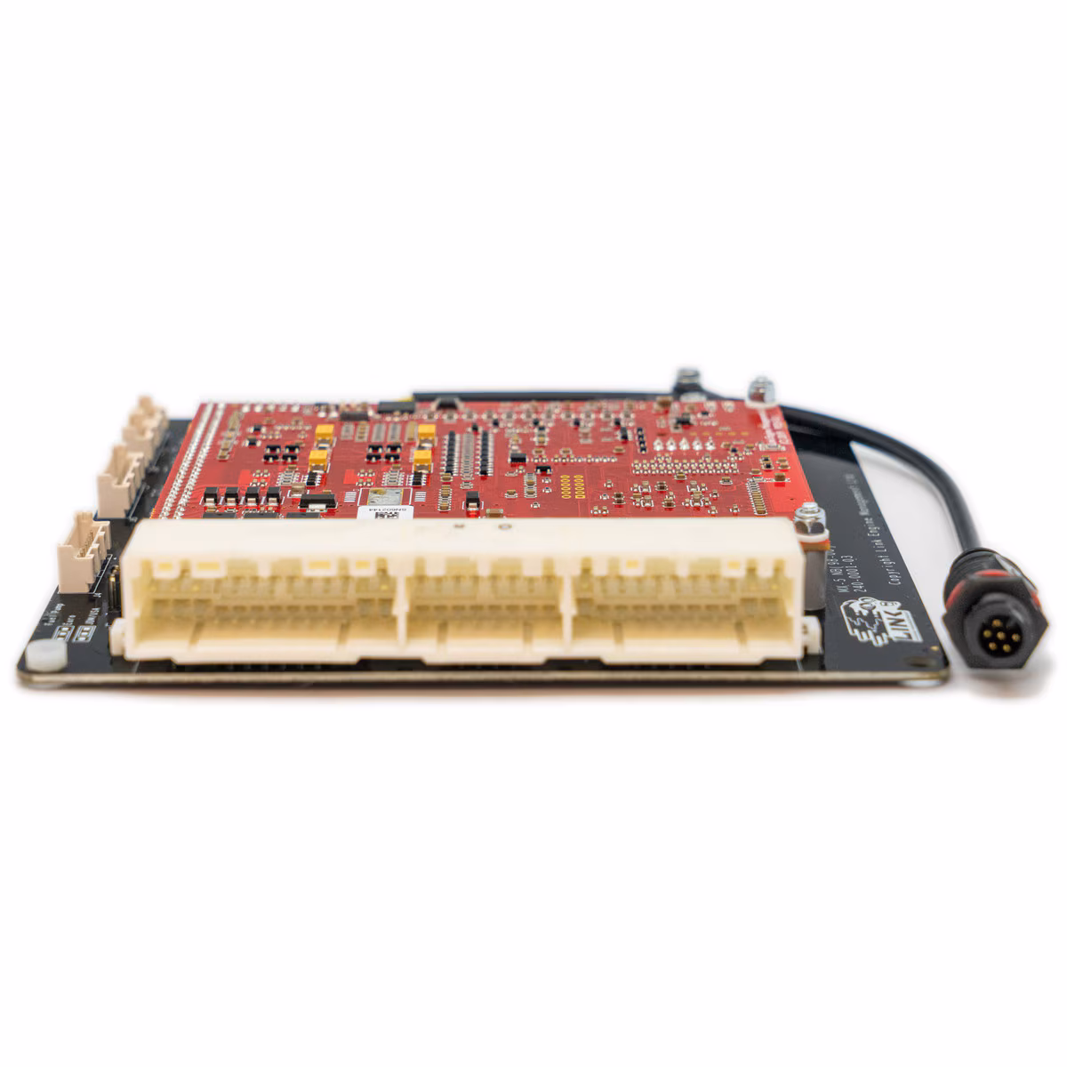
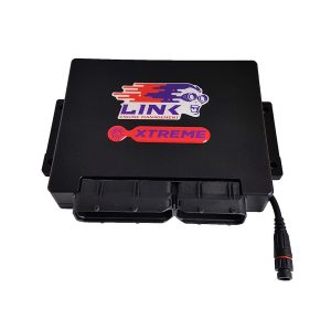
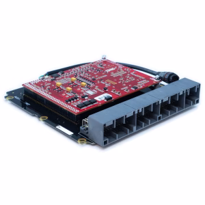
This ECU fits neatly inside the factory OEM enclosure. Installation is straightforward, with no alteration of the factory wiring loom required for the models listed below.
Designed for the Pre-Facelift Mazda MX5 NB (MY1998–2000, 3 Plug ECU, Non-VVT 1.8L Engine).
Before purchasing, please check that your connector matches the header shown in the product photo.
This ECU is for manual transmission models only.
Includes an onboard 7-bar MAP sensor.
Most factory features are supported.
Refer to the features tab for I/O expansion options.
Note: This Plug-In features a new 4-pin powered CAN connector and cannot use the old CANPCB cable.
Use the CANJST4 (Link PN 101-0198) cable for connecting CAN devices.
This 4-pin connector provides CAN communication as well as a protected 12V power and ground supply for powering CAN devices.
The power supply is protected by a self-resetting fuse rated at 3A continuous.
G4X Plug-In Key Features (where applicable)
Up to 6D fuel and ignition mapping
Precision closed loop cam control (four cam, independent control)
Sequential fuel delivery
Digital triggering, all OEM patterns
OEM idle hardware supported
5D boost control with three switchable tables
Motorsport features – antilag, launch, flat shift
Continuous barometric correction (on board)
CAN port
QuickTune – automated fuel tuning
Individual cylinder correction
USB tuning cable included
Stats recording into on-board memory
Gear compensations for spark, boost and fuel
Real time selectable dual fuel, ignition and boost maps
Sync and crank sensors can be a combination of Hall effect, variable reluctance or optical
Boost control referenced to gear, speed or throttle position
512 megabytes data logging memory
Staged injection
Knock control with “windowing”
I/O Expansion Options
Expansion Connector 1
Pin 1 – An Temp 4
Pin 2 – An Temp 3
Pin 3 – DI 10
Pin 4 – DI 9
Pin 5 – DI 8
Pin 6 – DI 7
Pin 7 – IGN 4
Pin 8 – IGN 3
E-Throttle Connector
Pin 1 – Ground (Signal)
Pin 2 – +5V Out
Pin 3 – An Volt 12
Pin 4 – An Volt 11
Pin 5 – An Volt 10
Pin 6 – An Volt 9
Pin 7 – Aux 10
Pin 8 – Aux 9
Related products
-
Sale!
Link G4X MiniLink MINIX, Mini Cooper ECU
Original price was: AUD $2,483.45.AUD $2,365.00Current price is: AUD $2,365.00. -
Sale!
Link ECU Plugin G4X Honda S2000 AP1 – 233-4000
Original price was: AUD $2,593.45.AUD $2,469.95Current price is: AUD $2,469.95. -
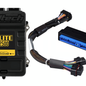
Haltech Elite 2500 + Nissan Skyline R32/33/R34 GT-R Plug’n’Play Adaptor Harness Kit
AUD $3,410.00 -
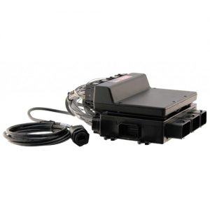
MoTeC NISSAN R35 GT-R ENGINE PLUG-IN ECU RHD KIT (ACTIVATED + LICENCE)
AUD $8,329.43